Spa Pack and Pump Setup and Install Instructions
Spa Pack and Pump Assembly Instructions
Please read the complete Owner’s manual provided and this overview before starting the installation.
Hot Tub Essentials will wire your circuit voltages (as per your order) and set up any dip switches (if applicable), so you shouldn't have to change these.
1) Remove control pack and pump from packaging – be careful not to discard any parts wrapped in paper or bubble wrap.
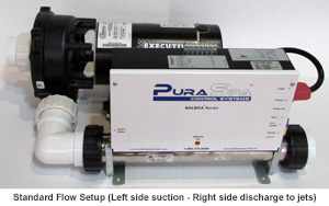
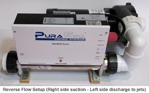
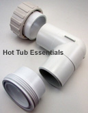
2) Turn the wet end of the pump (the discharge can be turned 90 degrees in either direction). Turn whichever direction makes the spa pack install easier for your hot tub. Turn the appropriate direction for "Standard Flow" or "Reverse Flow" as per the pictures below:
|
Standard Flow: Looking at the front suction |
Reverse Flow: Looking at the front suction |
|
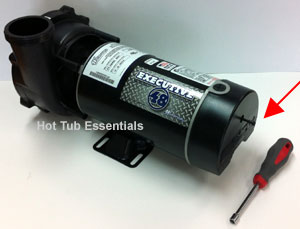
Turning the wet end is easy, once you know the bolt heads, that hold the wet end in place, are on the back of the electrical end of the motor. On most 48 frame pumps, you first have to remove a cover on the back of the motor, which is held in place with a 1/4" bolt. |
|
|
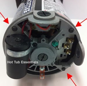
Once you remove the electrical cover, you will see four 1/4" bolts on the outer edge of the motor. 56 frame motors usually have four 5/16" bolts and do not have a cover hiding the bolts. It is best to place the motor on a block of wood so the wet end will turn freely. Then simply loosen all 4 bolts and pull them out an inch or so to make sure they are loose. Then turn the wet end the direction you require and tighten the bolts. It is best to use a nut driver (like in the top picture) to tighten the bolts. The bolts should be snug, but be careful not to over-tighten. |
|
3) Use a large flat screw driver to remove the threaded plastic plug in the side electrical access of the motor. Then thread in the metal cable connector (provided) and tighten the locking nut in place.
4) Wire the pump cord on your 2-speed pump. Use the 4 wire cord with the red plug end. Quick connectors are already installed on the pump cord wires. Feed the 4 wires through the cable connector you installed in step 3 and consult the wiring diagram on the side of the motor. The diagram will refer to the electrical connections on the motor, which are labeled to match the diagram.
The wire color for high and low speed is different on all spa packs, so be careful to wire your pump correctly. Mixing up the high and low speed wires will cause erratic behavior. Refer to the chart below for your spa pack model:
|
Spa Pack Model |
2-Speed Pump Cord - Wire Colors |
|
MX-1000, MX-3000 & most Balboa controls |
Low Speed - Black Wire |
|
PX-2000 (Mechanical Air button systems) & most Gecko controls |
Low Speed - Red Wire |
5) Place pump on rubber mount and put in position. Place spa pack in position. Use blocks to shim your equipment level (not included):
-
For Standard Flow setups, use a 3/4" thick block only under the pump mount.
-
For Reverse Flow setups, use 3/4" blocks only under the spa pack mounting legs.
Do not secure equipment at this time (leave loose until after gluing all fittings and tightening all pump and heater unions).
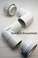
6) Use PVC primer and glue to connect elbow assembly.
|
For Standard Flow, glue fittings as pictured on the right |
|
|
For Reverse Flow, glue fittings in order pictured on the right. |
|
7) Connect the elbow assembly to your pump and heater (with proper o-rings).
8) Thread on the additional pump and heater union (with proper o-rings) and use PVC primer and glue to connect to hot tub. If hot tub has 1-1/2" plumbing, glue reducer fittings into this pump and heater union and then connect to the 1-1/2" plumbing.
9) Have your electrician hook up the main power to your spa pack using a properly sized GFCI and wire. Also have your electrician run a solid copper #8 gauge wire (not included) from the grounding terminal on the spa pack to the grounding terminal on the pump motor. Then plug in pump cord to spa pack.
10) Tighten all pump and heater unions. Use screws to secure the spa pack and pump.
11) Fill hot tub with water. If your spa has a pressurized filter canister, open the bleed valve to remove air. Turn on power to spa. Turn on pump and check to see that you have good flow coming out of the jets (it is common to have an air lock, so you may have to bleed air out of the lines).
To bleed air out of the lines, briefly open the highest bleed valve on the pump. If you have a stubborn air lock, you may have to bleed from the large threaded pump and heater unions. You can also try altering between low and high speeds, while also playing with the venturi air dials, until you have good flow coming out of the jets (good flow is required for the heater to work).